Thursday, April 19, 2018

The Hitchhiker's Guide for Learning to Auto CAD - Layouts

Layouts 
Display one or more scaled views of your design on a standard-size drawing sheet called a layout.
After you finish creating a model at full size, you can switch to a paper space layout to create scaled views of the model, and to add notes, labels, and dimensions. You can also specify different linetypes and line widths for display in paper space.

Model Space and Paper Space

As you know, you create the geometry of your model in model space.
Originally, this was the only space available in AutoCAD. All notes, labels, dimensions, and the drawing border and title block were also created and scaled in model space.
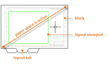
After paper space was introduced, you could click a layout tab to access a space designed specifically for layouts and scaling. In the following illustration, paper space is active. There are currently only two objects in paper space: a drawing border block, and a single layout viewport, which displays a view of model space.
Working with layout viewports is described in more detail later in this topic.

Four Methods for Scaling

There are four different methods in AutoCAD that are used to scale views, notes, labels, and dimensions. Each method has its advantages depending on how the drawing will be used. Here's a brief summary of each of the methods:
  • The Original Method. You create geometry, annotate, and print from model space. Dimensions, notes, and labels must all be scaled in reverse. You set the dimension scale to the inverse of the plot scale. With this method, scaling requires a little math. For example, a common scale used in architecture is 1/4" = 1'-0" which is 1:48 scale. If a note is to be printed ¼" high, then it must be created 48 times as large, or 12" high in model space. The same scale factor also applies to dimensions, and an ARCH D drawing border at that scale is 144 feet long. When the drawing is printed as a D-size sheet, everything scales down to the correct size.
    Note: Many AutoCAD drawings were created with this method, and many companies still use it. Once everything is set up, the method works well for 2D drawings with single views and inserted details.
  • The Layout Method. You create geometry and annotate in model space, and print from the layout. Set the dimension scale to 0 and the dimensions will scale automatically.
  • The Annotative Method. You create geometry in model space, create annotative dimensions, notes, and labels (using a special annotative style) in model space from the layout, and you print from the layout. Annotative objects display only in layout viewports that share the same scale. The dimension scale is automatically set to 0 and all annotative objects scale automatically.
  • The Trans-Spatial Method. You create geometry in model space, create annotations in paper space on a layout with dimension scale set to 1, and you print from the layout. This is arguably the easiest, most direct method, and it is the method of choice for this guide.
Talk to other AutoCAD users in your discipline about these four methods and why they chose the method that they use.

Specifying the Paper Size of a Layout

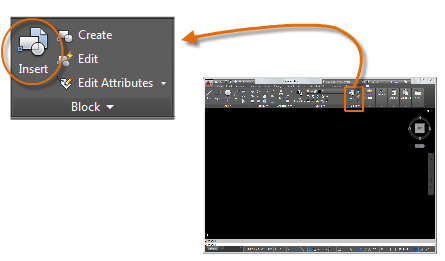
The first thing that you should do when you access a layout tab (1) is right-click the tab (2) and rename it (3) to something more specific than Layout 1. For a D-size layout, ARCH D or ANSI D might be good choices.
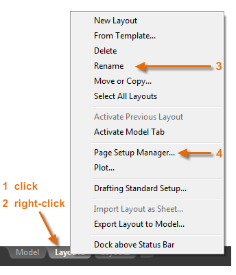
Next, open the Page Setup Manager (4) to change the paper size displayed in the layout tab.
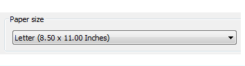
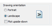
Note: You might be wondering why there are two entries in the list for every sheet size. This is because some printers and plotters do not recognize the drawing orientation setting.

Layout Viewports

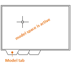
A layout viewport is an object that is created in paper space to display a scaled view of model space. You can think of it as a closed-circuit TV monitor that displays part of model space. In the illustration, model space is active and accessible from within the current layout viewport.
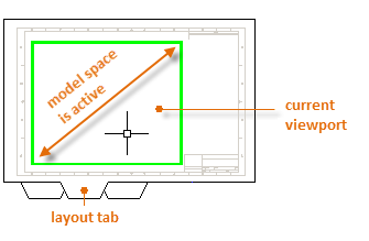
In a layout, when model space is active, you can pan and zoom, and anything else that you could do on the Model tab.
Important: You can switch between paper space and model space by double-clicking inside or outside the layout viewport.
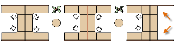
For example, let's say that you created a backyard deck design in model space, and now you want to lay out and print your design from a layout tab.
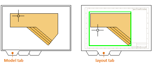
The view in the layout viewport is not yet set to the correct scale.
Note: You can use the MVIEW (make view) command to create additional layout viewports in paper space. With several layout viewports, you can display several views of model space at the same or at different scales.

Scaling Views and Trans-Spatial Annotation

Here are the steps to follow if you use the trans-spatial method of annotating your drawing:
  1. Click the layout tab. If you started the drawing with your own custom drawing template file, several tasks might already have been completed: the layout might already be set to D-size, and the title block might already have been inserted in the layout.
  2. By default, paper space is active, so double-click within the layout viewport to make model space active. Notice that the edge of the layout viewport becomes thicker as a result of switching to model space.
  3. Zoom out and center the model space view by panning. However the displayed view is still not set to the correct scale.
  4. Double-click outside the layout viewport to make paper space active again.
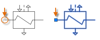
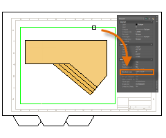
  5. Open the Properties palette and then click to select the edge of the layout viewport.
  6. In the Properties palette, specify a standard scale of 1/4" = 1'-0" from the drop-down list. This action scales your view of model space precisely to the D-size drawing. You also set the Display Locked property from No to Yes. This prevents any unintentional display changes to the view.
  7. Note: By default, the dashes and spaces in a non-continuous linetype appear at the same length regardless of the scale of the layout viewport.
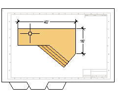
  8. Move the layout viewport as needed, and adjust its edges using grips.
  9. Create notes, labels, and dimensions directly in paper space. They automatically appear at the correct size.
  10. Turn off the layer on which you created the layout viewport object. This hides the edges of the layout viewport as shown below.
  11. Print the drawing to paper or as a DWF or PDF file.
Note: After you have finished dimensioning, you can use the EXPORTLAYOUT command to merge everything in model and paper space into the model space of a separate drawing file. This operation creates a drawing file that conforms to the original method of creating the model and all annotations in model space.

The Hitchhiker's Guide for Learning to Auto CAD - Blocks

Blocks

Insert symbols and details into your drawings from commercial online sources or from your own designs.
In AutoCAD, a block is a collection of objects that are combined into a single named object. The following are some sample blocks at various scales.
Some of these blocks are realistic representations of objects, some are symbols, and one of them is an architectural title block for a D-size drawing.

Insert a Block

Typically, each of these blocks is an individual drawing file, perhaps saved in a folder with similar drawing files. When you need to insert one into your current drawing file, you use the INSERT command (or enter I in the Command window).
The first time you insert the drawing as a block, you need to click Browse to locate the drawing file. Make sure you organize your blocks into easy-to-find folders.
Once inserted, the block definition is stored in your current drawing. From then on, you can choose it from the Name drop-down list without needing to click the Browse button.
Tip: The default settings in the Insert dialog box are usually acceptable. After you choose the block name, click OK, and then specify its location in your drawing. You can rotate it later, if necessary.
Notice that when you insert a block, it is attached to your cursor at the point indicated. This location is called the insertion point. By default, the insertion point is the origin point (0,0) of the original drawing.
After inserting the block, you can select it and a grip appears. You can easily move and rotate this block using this grip.
In the following example, a drawing file is inserted into the current drawing to provide a standard detail view.
Note: Inserting a drawing file as a block provides a static reference to the specified drawing. For a reference that automatically updates, you can attach the drawing with the External References palette (XREF command) instead.

Create a Block Definition

Instead of creating a drawing file to be inserted as a block, you might want to create a block definition directly in your current drawing. Use this method if you do not plan to insert the block into any other drawing. In that case, use the BLOCK command to create the block definition.
For example, this is how you could create a module for a cubicle design.
  1. Create the objects for the block.
  2. Start the BLOCK command.
  3. Enter a name for the block, in this case Quad-Cube.
  4. Select the objects that you created for the block (click 1 and 2).
  5. Specify the block insertion point.
You can enter the information for steps 3, 4, and 5 into the Block Definition dialog box in any order.
After creating the block definition, you can insert, copy, and rotate the block as needed.
Using the EXPLODE command, you can explode a block back to its component objects if you need to make changes. In the illustration below, the cubicle on the right was exploded and modified.
In this example, you would probably create a new block definition from the objects in the exploded block.
Note: You can create block definitions that include one or more attributes that store and display information. The command that you would use is ATTDEF. Typically, attributes include data such as part number, name, cost, and date. You can export block attribute information to a table or to an external file.

Recommendations

There are several different schemes for saving and retrieving block definitions.
  • You can create an individual drawing file for each block that you intend to use. You save these drawing files in folders, each of which would contain a family of related drawing files.
  • You can include the block definitions for title blocks and common symbols in your drawing template files to make them available immediately when starting a new drawing.
  • You can create several drawing files, which are sometimes called block library drawings. Each of these drawings contains a family of related block definitions. When you insert a block library drawing into your current drawing, all the blocks that are defined in that drawing become available.


For Video Coaching Please Click the Below Link


https://youtu.be/0rmJy0XCOsY 

Sunday, April 15, 2018

The Hitchhiker's Guide for Learning to Auto CAD - Notes and Labels


Create notes, labels, bubbles, and callouts. Save and restore style settings by name.
You create general notes using the MTEXT command (or enter MT in the Command window), which stands for multiline text. The multiline text tool is available on the Annotation panel.B


After you start the MTEXT command, you are prompted to create a "text box" with two diagonal clicks.


The exact size of the text box is not that important. After you specify the text box, the In-Place Editor is displayed and you can easily change the length and width of the note before, during, or after typing the text.


All the usual controls are available in the In-Place Editor, including tabs, indents, and columns. Also notice that when you start the MTEXT command, the ribbon temporarily changes, displaying many options such as text styles, columns, spell checking, and so on.
·         To exit the text editor after you finish entering the text, click anywhere outside it.
·         To edit a note, simply double-click it to open the text editor.
TIP:You can use the Properties palette to control the text style used for one or more selected multiline text objects. For example, after selecting five notes that use different styles, click the Style column and choose a style from the list.


Create a Text Style
As with several other annotation features, multiline text provides a lot of settings. You can save these settings as a text styleusing the STYLE command, and then you can access the text styles you've saved by clicking the drop-down arrow on the Annotation panel. The current text style is displayed at the top of the drop-down list.
To create a new text style, click the Text Style control as shown.


When you create a new text style, you give it a name, and then choose a font and a font style. The order in which you click the buttons is shown below:


TIP:Save any new or changed text styles in your drawing template files. This will save you a lot of time by making them available in all new drawings.
Multileaders
Multileader objects are used to create text with leader lines such as general labels, reference labels, bubbles, and callouts.


Create a Multileader
To create a multileader, use the MLEADER command. Click the Multileader tool in the Annotation panel or enter MLD in the Command window. Follow the prompts and options in the Command window. Feel free to experiment.
After you create a multileader, select it and then modify it by clicking and moving its grips.


Grip menus appear when you hover over arrowhead and leader grips. From these menus, you can add leader segments or additional leaders.


You can edit the text in a multileader by double-clicking it.
Create a Multileader Style
You can create your own multileader styles from the drop-down list in the expanded Annotation panel, or by entering MLEADERSTYLE in the Command window.


For example, to create a "detail callout" style, start the MLEADERSTYLE command. In the Multileader Styles Manager, click New and choose a descriptive name for the new multileader style. Click the Content tab, choose Block, and then Detail Callout as shown.


NOTE:As with text styles, once you create one or more multileader styles, save them in your drawing template files.

For Video Coaching Please Click the Below Link


https://youtu.be/0rmJy0XCOsY 


The Hitchhiker's Guide for Learning to Auto CAD - Modifying

Perform editing operations such as erase, move, and trim on the objects in a drawing.
The most common of these tools are located on the Modify panel of the Home tab. Take a minute to look through them.


Erase
To erase an object, use the ERASE command. You can enter E in the Command window, or click the Erase tool. When you see the cursor change to a square pickbox, click each object that you want to erase, and then press Enter or the Spacebar.
NOTE:Alternatively, before you enter any command, you can select several objects and then press the Delete key. Experienced AutoCAD users often use this method as well.
Select Multiple Objects
Sometimes you need to select a large number of objects. Instead of selecting each object individually, you can select the objects in an area by clicking an empty location (1), moving your cursor right or left, and then clicking a second time (2).

·         With a crossing selection, any objects within or touching the green area are selected.
·         With a window selection, only the objects completely contained within the blue area are selected.
The result is called the selection set, the set of objects that will be processed by a command.
TIP: You can easily remove objects from the selection set. For example, if you select 42 objects, and two of them should not have been selected, hold down Shift and then select the two that you want to remove. Then, press Enter or the Spacebar, or right click to end the selection process.
NOTE:Clicking and dragging results in a different selection method called lasso selection.
Move and Copy
Here's how you would use the COPY command to lay out a row of decorative tiles. Starting with a polyline that represents its shape, you need to make copies that are 1/8" apart.


You click the Copy tool or enter CP in the Command window to start the command. From here, you can choose between two primary methods, depending on what's more convenient. You will use these two methods frequently.


The Distance Method
In this case, you know that any point on the second tile will be a total of 9-7/8" + 1/8" = 10" from the equivalent point on the original tile. So, you select the tile, press Enter or the Spacebar to end your selection, and click anywhere in the drawing area (1). This point does not have to be located on the tile.


Next, you move your cursor to the right, relying on the polar tracking angle to keep the direction horizontal, and then enter 10 for the distance. Press Enter or the Spacebar a second time to end the command.
When you specified a distance and a direction from a point (1), you defined a vector. This vector was applied to the tile that you selected.
The Two Points Method
Another method, one that you will often use when you don't want to add numbers together, requires two steps. You start the COPY command and select the tile as before, but this time you click the two endpoints as shown. This also defines a vector.


TIP:The two points that define a vector don't need to be located on the object that you want to copy. You can use two points specified anywhere in your model.
Next, to add the 1/8" space between the tiles, click the Move tool or enter M in the Command window. The MOVE command is similar to the COPY command. Select the newly copied tile, and press Enter or the Spacebar. As before, click anywhere in the drawing area and move your cursor to the right. Enter 1/8 or .125 for the distance.
Create Multiple Copies
You can use the two-points method as a repeating sequence. Let's say that you want to make more copies of the circle at the same horizontal distance. You start the COPY command and select the circle as shown.


Then, using the Center object snap, click the center of circle 1, followed by the center of circle 2, and so on.


For larger numbers of copies, try experimenting with the Array option of the COPY command. For example, here's a linear arrangement of deep foundation piles. From a base point, you specify number of copies and the center-to-center distance.

Offset
Most models include a lot of parallel lines and curves. Creating them is easy and efficient with the OFFSET command. Click the OFFSET tool or enter O in the Command window.


Select the object (1), specify the offset distance, and click to indicate on which side of the original that you want the result (2). Here is an example of offsetting a polyline.


TIP: A fast way to create concentric circles is to offset them.
Trim and Extend
A popular technique is to use the OFFSET command in combination with the TRIM and EXTEND commands. In the Command window, you can enter TR for TRIM or EX for EXTEND. Trimming and extending are some of the most commonly used operations in AutoCAD.


In the following illustration, you want to extend the lines that represent the steps for this deck. You start the Extend command, select the boundary, and then press Enter or the Spacebar.


Pressing Enter or the Spacebar tells AutoCAD that you've finished selecting the boundaries, and that you're now ready to select the objects to be extended.
TIP:A faster method is to press Enter or the Spacebar right away instead of selecting any boundary objects. This forces AutoCAD to consider all objects as possible boundaries.
Next, you select the objects to be extended (near the ends to be extended), and then you press Enter or the Spacebar to end the command.


The result is that the lines are extended to the boundary.


The TRIM command follows the same steps, except that when you select the objects to trim, you select the portions to trim away.
Mirror
The following illustration comes from a tile project. The walls in this residential bathroom are flattened out to be able to lay out the tile pattern and estimate the number of tiles needed.


You can save a lot of work by taking advantage of the symmetry between the left and right walls. All you need to do is create the tiles on one wall and then mirror the wall across the center of the room.
In the example below, you start the MIRROR command (or enter MI in the Command window), use window selection (1 and 2) to select the geometry on the right wall, and then specify a mirror line (3 and 4) corresponding to the centerline of the bathroom.


Finally, decline the option to "Erase source objects" by pressing Enter or the Spacebar.


TIP: Always look for symmetry to save yourself extra work, even if the symmetry is not 100% identical.
Stretch
You can stretch most geometric objects. This lets you lengthen and shorten parts of your model. For example, this model might be a gasket or the design for a public park.


Use the STRETCH command (or enter S in the Command window) and select the objects with a crossing selection as shown below (1 and 2). The crossing selection is mandatory—only the geometry that is crossed by the crossing selection is stretched. Then click anywhere in the drawing area (3), move the cursor to the right, and enter 50 as the distance. This distance might represent millimeters or feet.


To shorten the model by a specified amount, you'd move your cursor to the left instead.
Fillet
The FILLET command (enter F in the Command window) creates a rounded corner by creating an arc that is tangent to two selected objects. Notice that the fillet is created relative to where you select the objects.


You can create a fillet between most types of geometric objects, including lines, arcs, and polyline segments.
TIP: If you specify 0 (zero) as the radius of the fillet (imagine a circle shrinking to a radius of 0), the result trims or extends the selected objects to a sharp corner.
Explode
The EXPLODE command (enter X in the Command window) disassociates a compound object into its component parts. You can explode objects such as polylines, hatches, and blocks (symbols).
After you explode a compound object, you can modify each resulting individual object.
Edit Polylines
You can choose from several useful options when you want to modify a polyline. The PEDIT command (enter PE in the Command window) is located on the drop-down list of the Modify panel.


With this command, you can
·         Join two polylines into a single polyline if they share a common endpoint
·         Convert lines and arcs into a polyline—simply enter PEDIT and select the line or arc
·         Change the width of a polyline
TIP: In some cases, the easiest method to modify a polyline is to explode it, make the modifications, and then turn the objects back into a polyline using the Join option of the PEDIT command.
Grips
Grips are displayed when you select an object without starting a command. Grips are often handy for light editing. For example, the line below accidentally snapped to the wrong endpoint. You can select the misaligned line, click on a grip and then click to specify the correct location.


By default, when you click a grip, AutoCAD is automatically in **STRETCH** mode as indicated in the Command window. If you want to explore other ways of editing objects with grips, press Enter or the Spacebar to cycle through several other editing modes. Some people perform most editing operations using grips.